Fairbairn-Sykes fighting knives

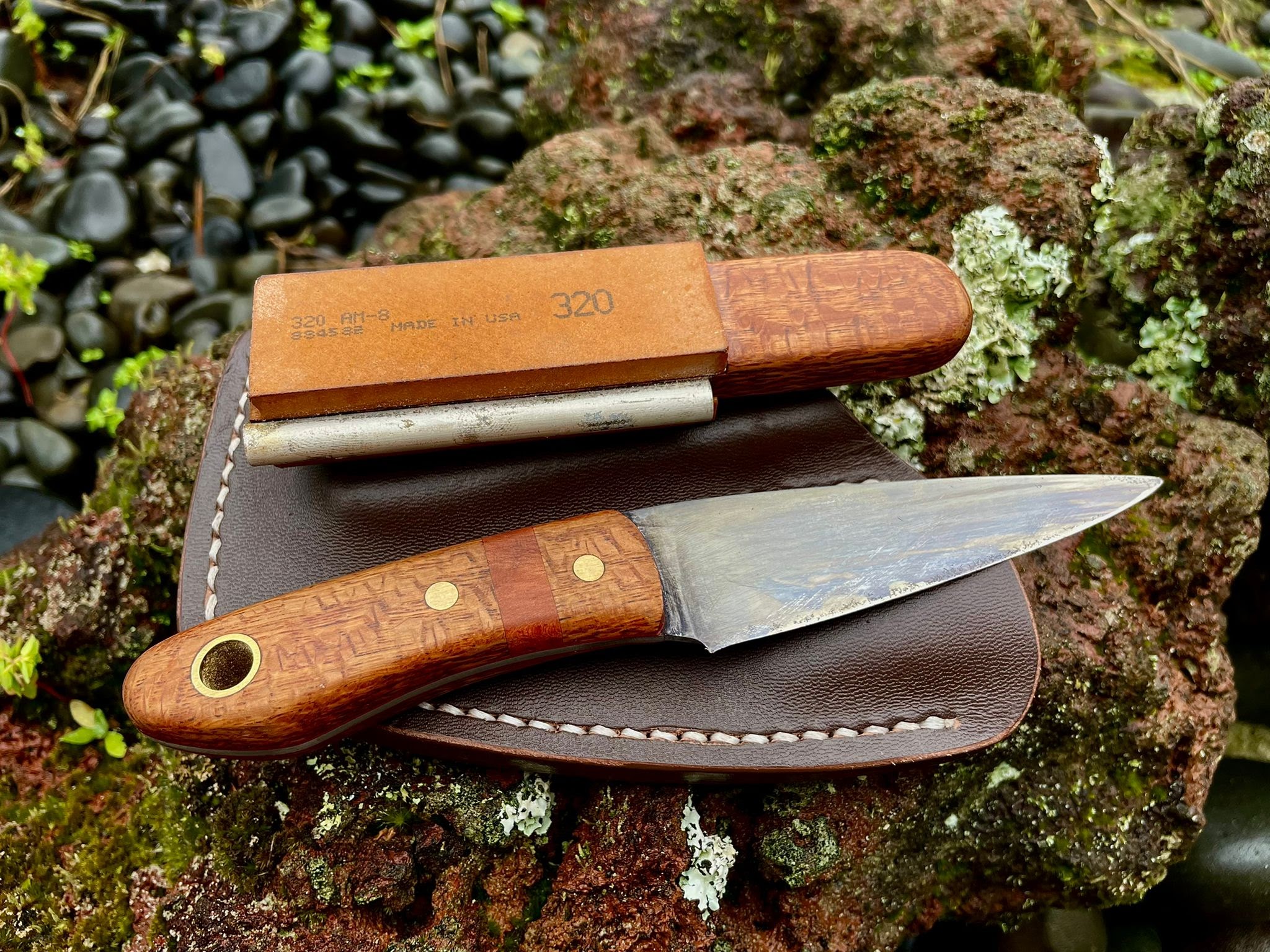
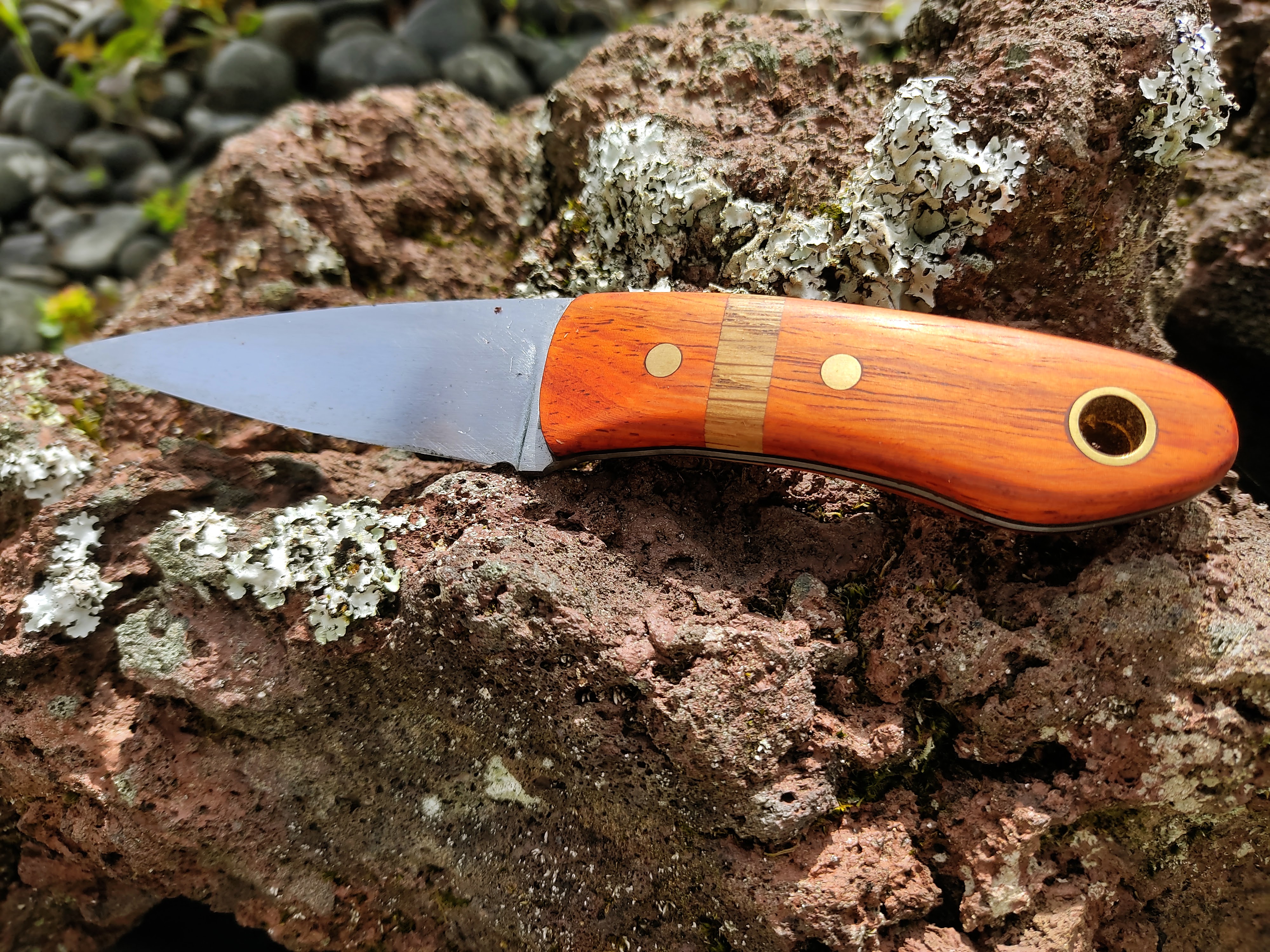
I found the history behind these knives to be quite interesting and also they look really cool so I thought I’d have a go at making some.

The original knife design used a brass handle with a round tang that goes through the pommel and is peened over. Rather than doing this, I decided to weld M4 threaded rod to the blade and machine a threaded brass pommel. I wanted to use a wooden handle, so the pommel would have to be fairly large in order to get the right balance.

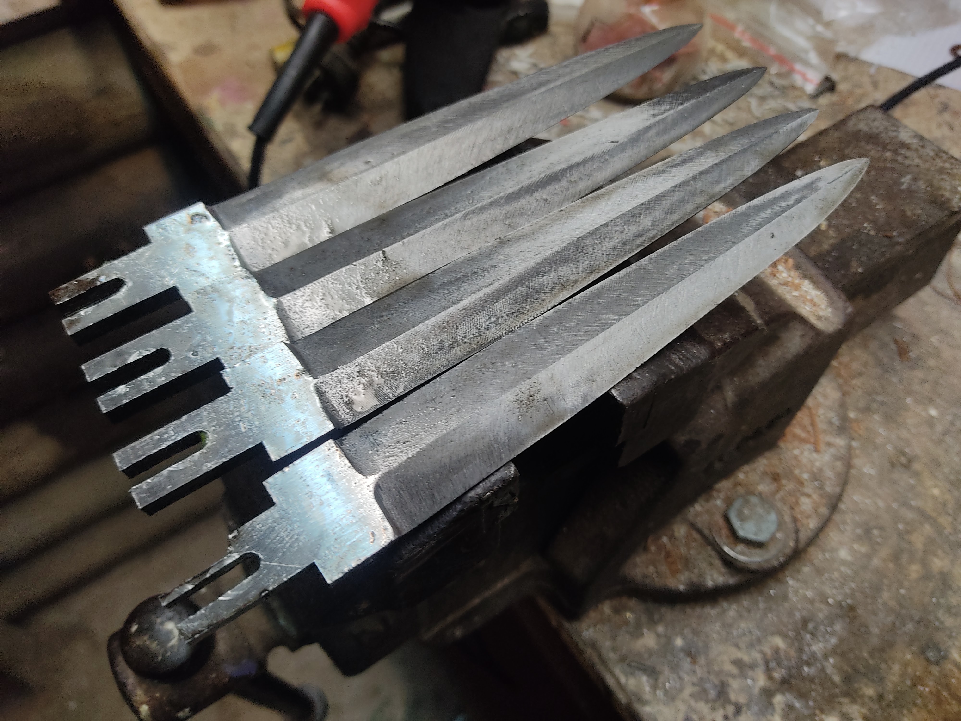
Starting with 1/4″ O1 steel, I cut with an angle grinder and shape with a linisher.

I used the same wooden fixture I sued to make my last set of hunting knives to get the bevels. I was initially worried about how I would get these to taper correctly but as long as you get the bevel angle right on the fixture, you can do everything else by eye and feel.

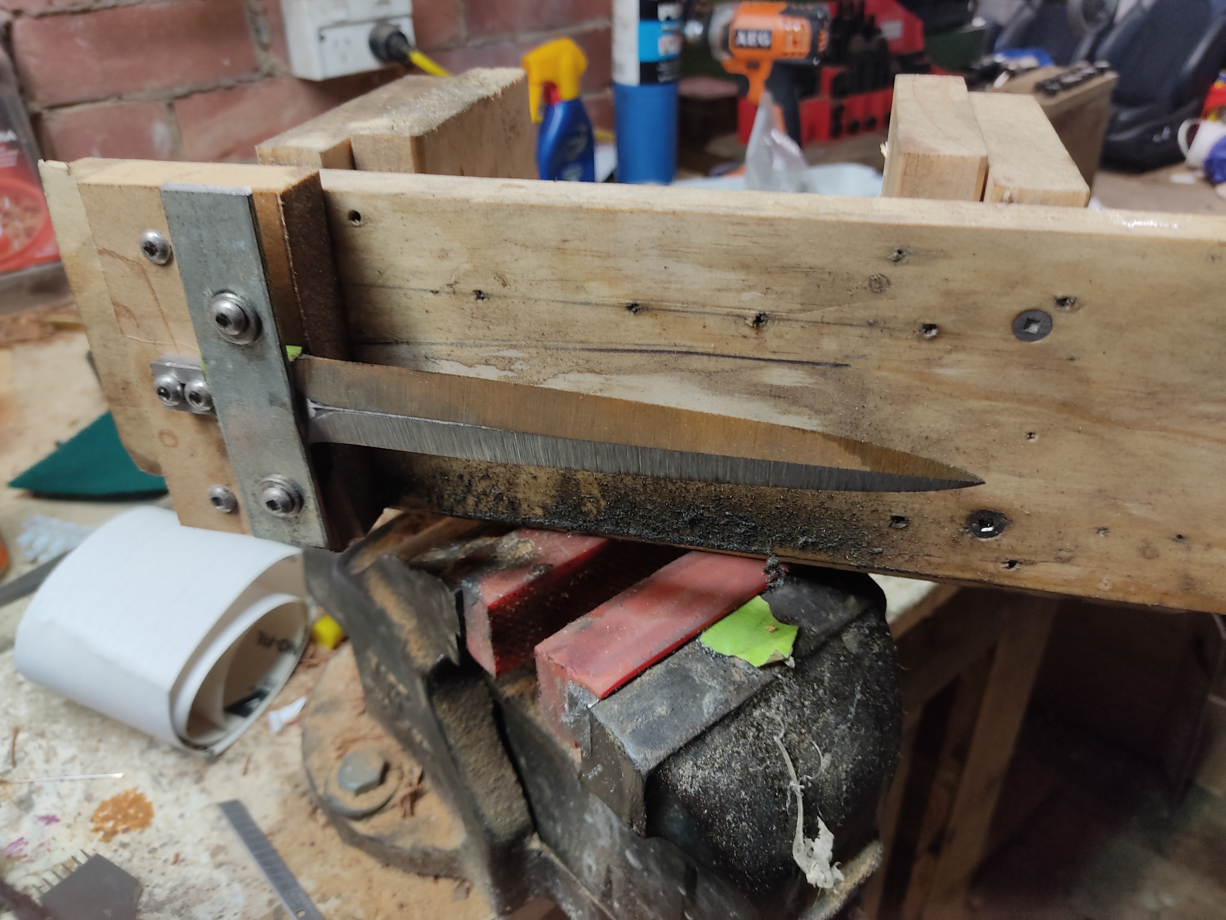
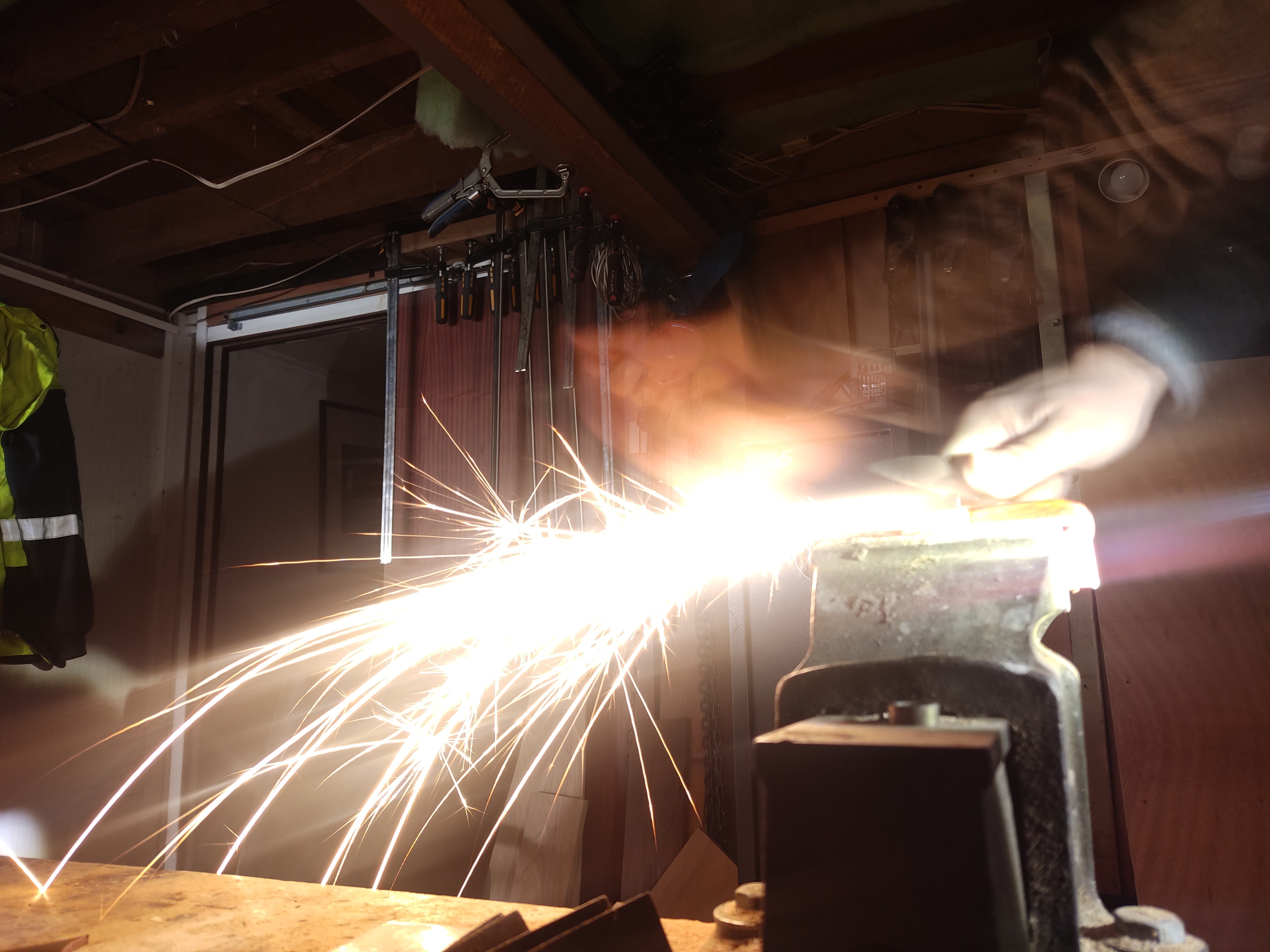
Below is a pic of my linishing setup as it stands. It’s not perfect for the job- Getting the plunges right requires tracking the belt over to which ever side I’m working on but I can’t justify buying an expensive setup right now.

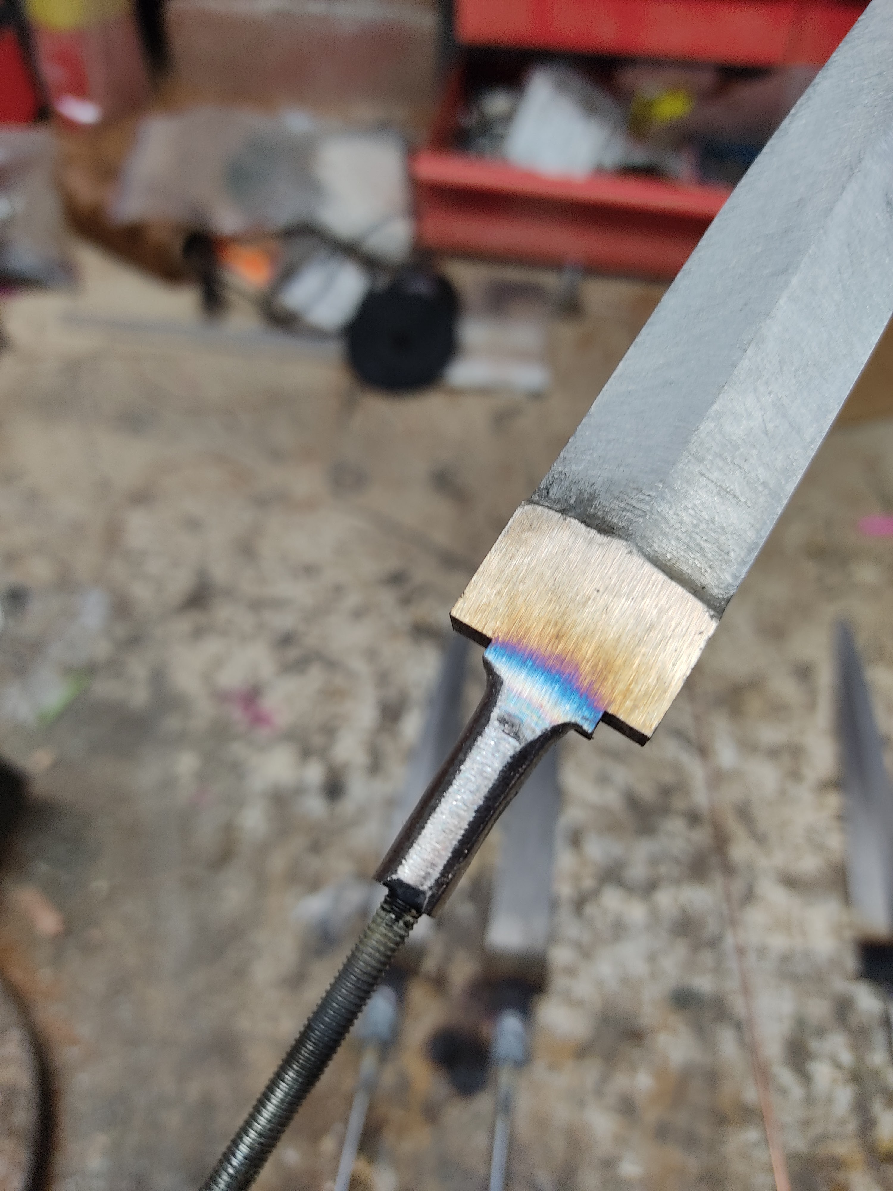
After grinding, I milled slots to weld in the threaded rod.

Photos of the welded in rod.

Next, I ground the tang down.

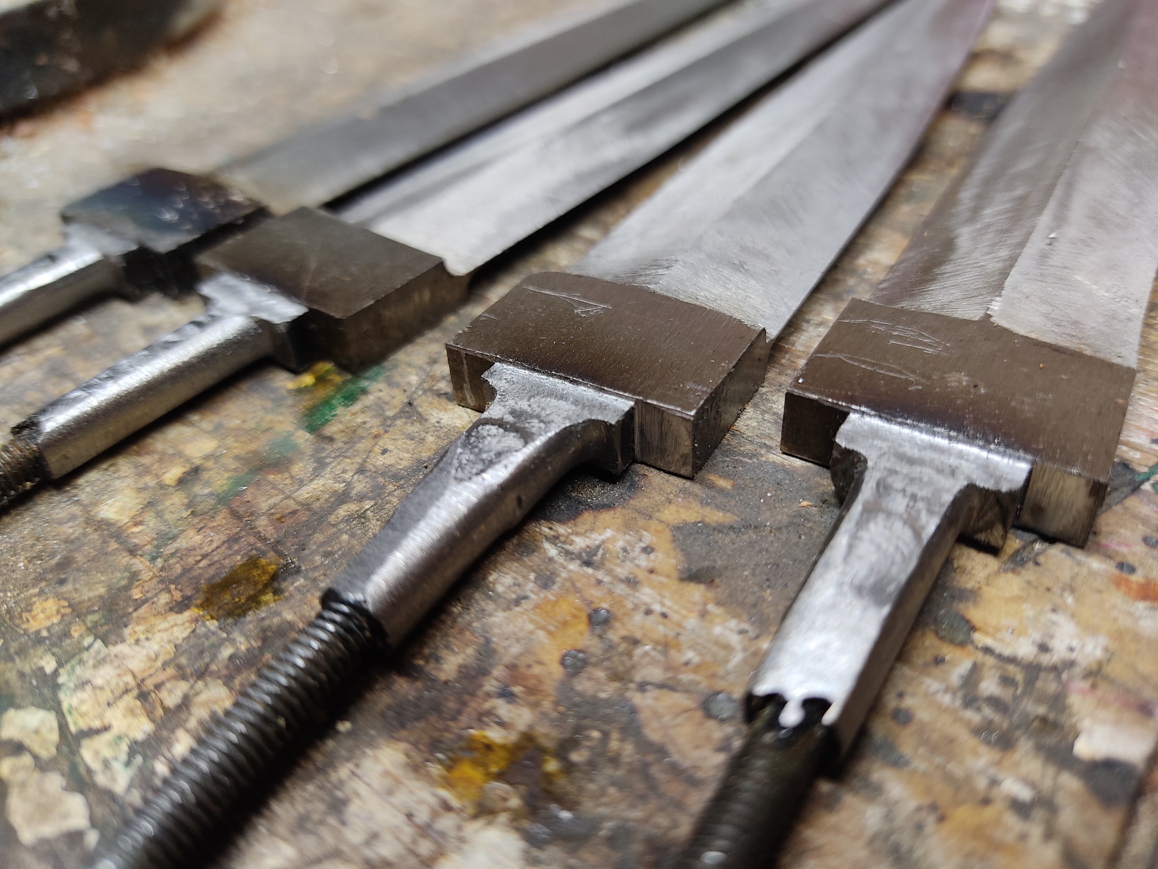
After this, I milled the faces of the tangs. The idea of this is that if I don’t get the slot perfect on the cross guard, it will be hidden beneath the shoulder on the tang. After this, I heat treated, finish ground and blued the blades.

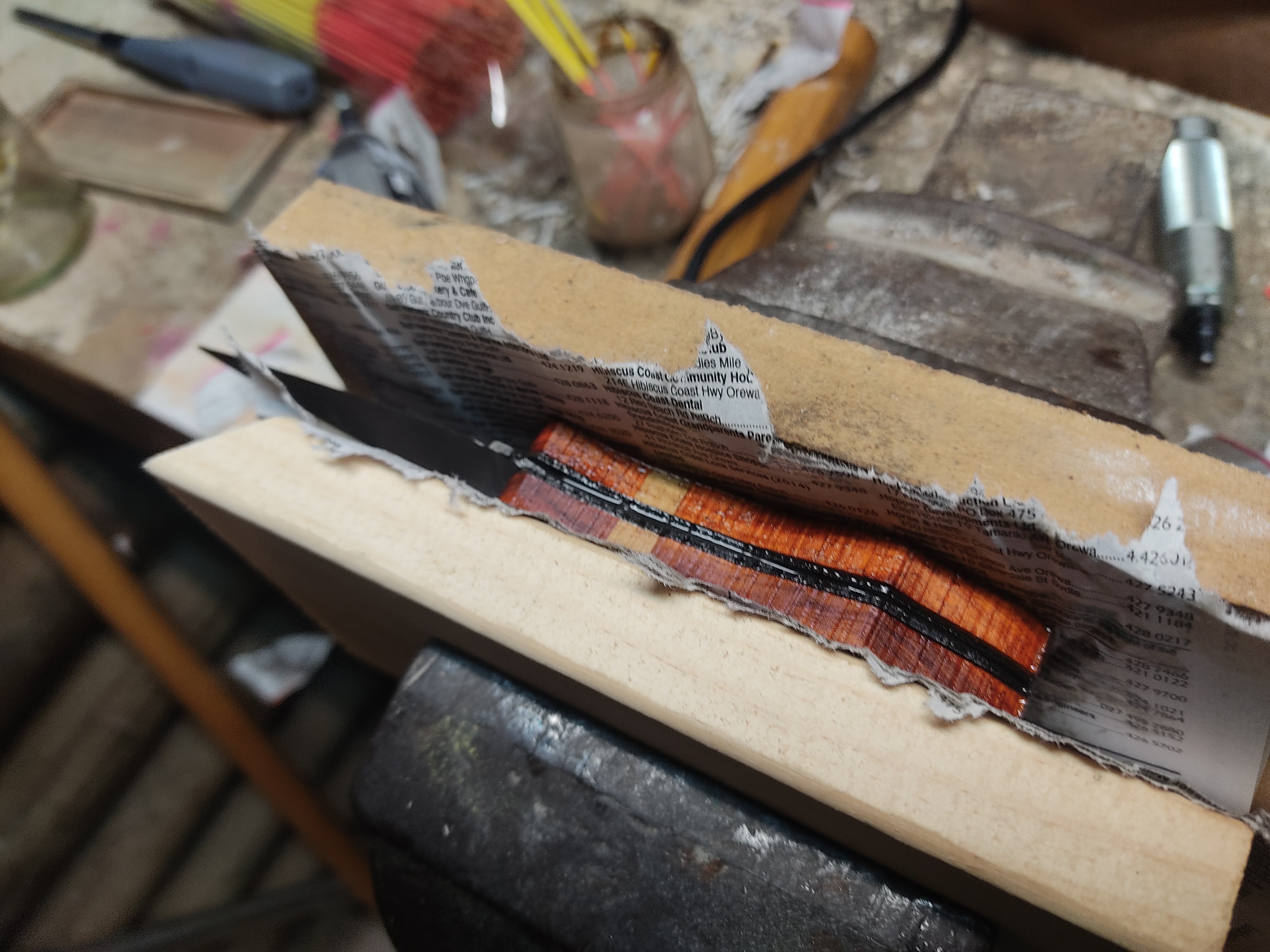
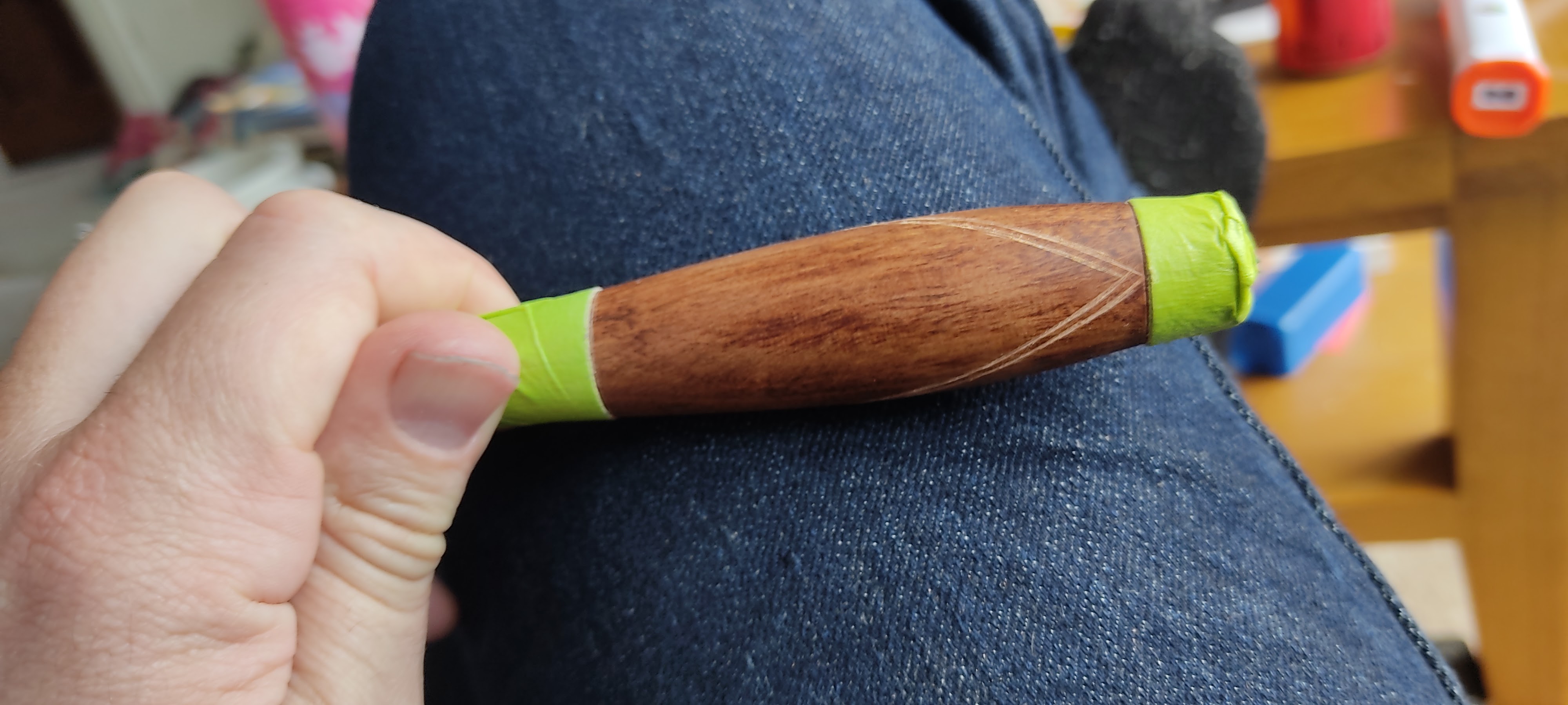
I wanted to make wooden handles so I turned the blanks up on my lathe and started checkering. I made a couple of practice pieces first and even then screwed up my first handle. The problem with checkering a shape like these handles is the difference in diameter in the middle of the knife versus the sides. You can either maintain consistent spacing on your checkering or your straight lines turn to curves that don’t match where they meet. I made a sketch below to explain. The initial line is straight buy they get more curved each time. You can mitigate this with your technique but I’ve not been able to eliminate it entirely. This means that by the time you wrap all the way around the knife, it’s highly unlikely that you will be able to match the lines up.

My solution is to groove a vertical line and use this as a divider so it doesn’t matter if the checkering matches up or not.

Photo of the other side

Now when checkering, you can reduce the amount of curve that is introduced by breaking a few rules. Instead of making a grid of light, pilot grooves and then deepening them, make a nice deep groove before using it as a reference for the next groove. If you have some depth to the groove, you can play around a little bit with the spacing between them by pushing the checkering tool to one side as you go. This is not normally good practice.

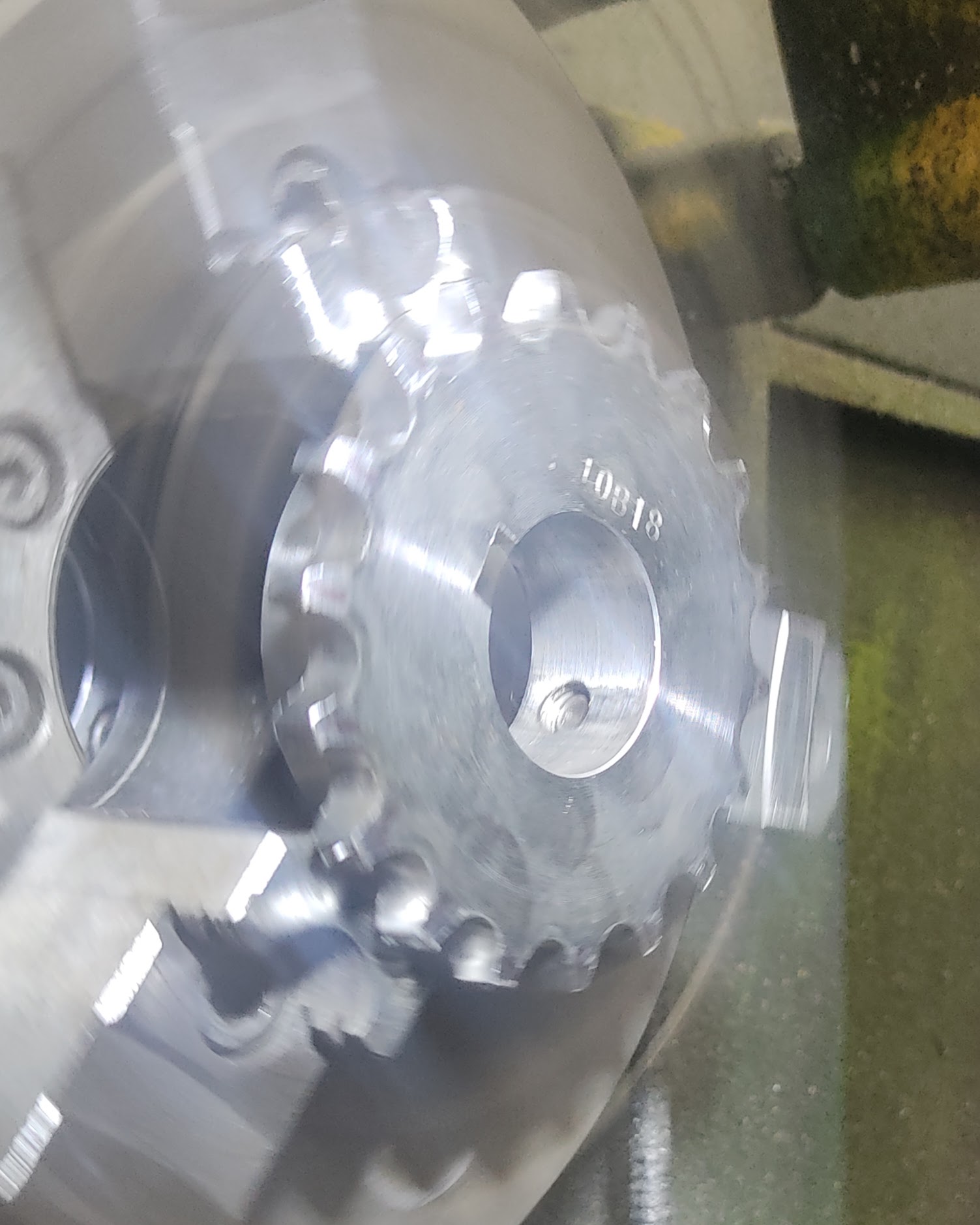
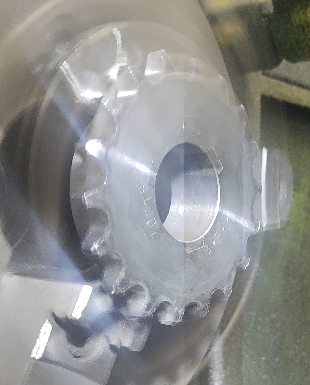
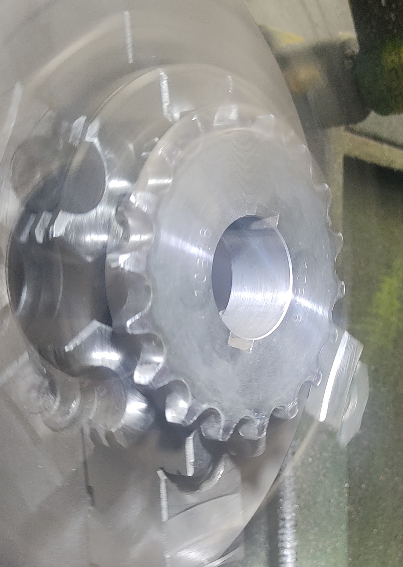
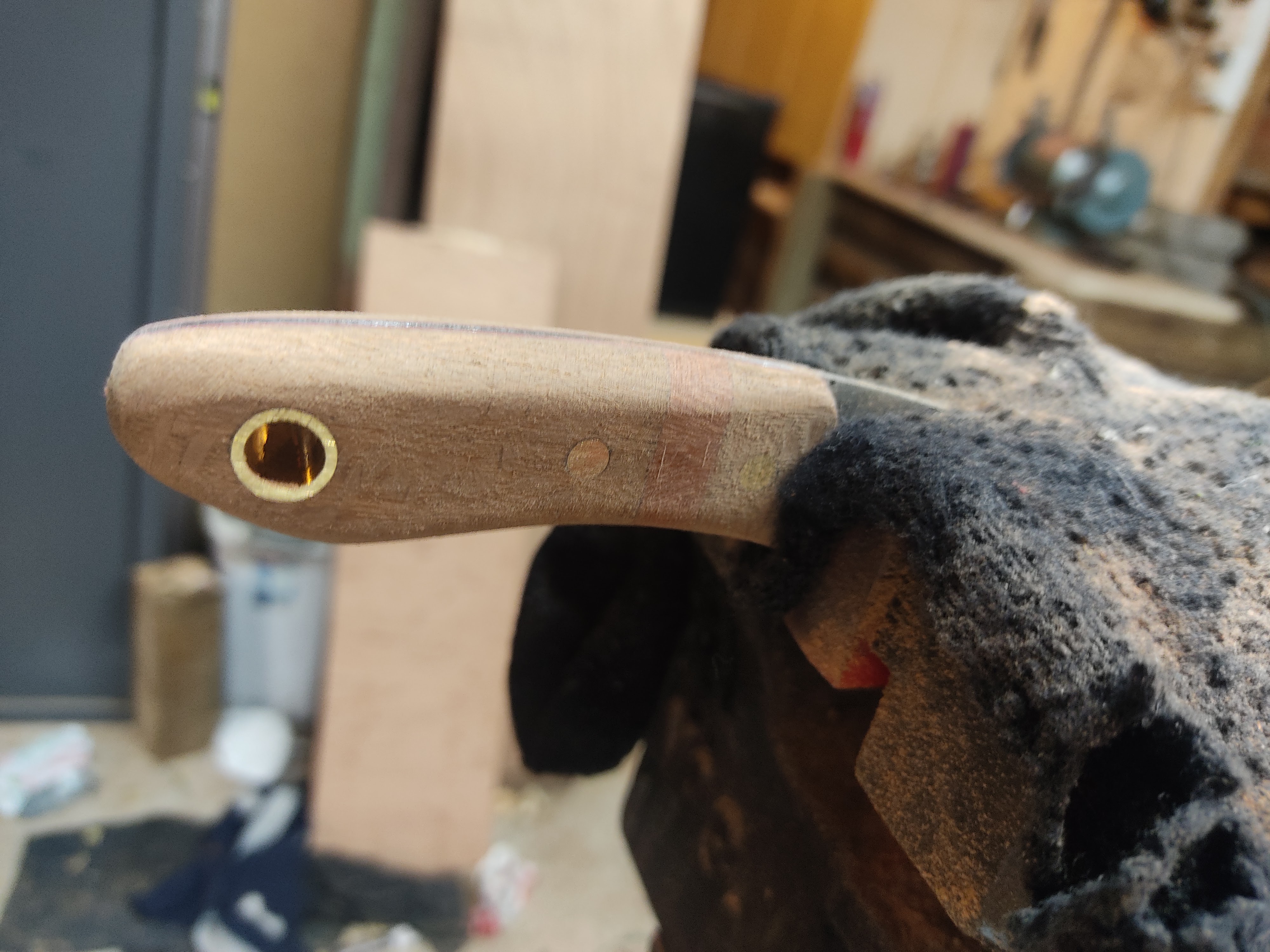
The pommels were turned up on a lathe. Not much more to say about that. The cross guards I slotted on my mill and filed the holes square. I then bolted 4 together through the slots and shaped them by eye.

Posted in Knives | Leave a comment

Inspecting machinery with a strobe

A large part of my current job involves inspecting machinery to ensure that it is operating correctly. However stopping a machine in order to inspect it is costly so there is a strong emphasis on running inspections to save this cost. One of the more common tools of this trade is the strobe light.

Unfortunately, there isn’t much in the way of resources out there that explain how to properly use these. What exactly are you looking for when using a strobe? While some applications are pretty simple and common sense- such as “freezing” a universal joint so that you can visually inspect it- how to you check for a worn keyway or a failing bearing?

I did some experiments to find out.

To simulate a bad bearing, I put a sprocket in the lathe. I first set it up nice and concentric. I started the lathe up at high speed- about 1800RPM and cranked the strobe to the point where the sprocket froze nicely. About 30Hz. Pic below.

Sprocket turning concentrically with strobe in sync

You can use a single repeating feature like a stamped part number or a keyway to confirm that you have the correct frequency if you are unsure of the rotational speed. I find it’s easiest to start the strobe too fast and slow it down until the part “freezes.” Below, I have the strobe set up at triple speed. You can see three keyways- or rather, three images of a single keyway. Then I slowed down until it froze again.

Sprocket turning concentrically with strobe at 3x frequency

Now I slowed down to double speed. You can see two keyways.

Sprocket turning concentrically with strobe at 2x frequency

The below image is with the strobe in sync again, but this time, I deliberately set the sprocket incorrectly in the chuck so that it wobbles as if it has a bad bearing. But it doesn’t look any different to the first image with the sprocket running true. This is because an eccentric part will wobble once per revolution so if you look at it once per revolution at the same point of rotation, it doesn’t look like it’s wobbling at all.

Sprocket turning eccentrically with strobe in sync

Now I set the strobe to double speed again. You can see that on this picture, there is now a slight ghosting. Looking closely around the outline of the sprocket, you can see a double outline. This is the indicator that something may be wrong.

Sprocket turning eccentrically with strobe at 2x frequency

Below, I have two images back to back to show more clearly the difference that you can see when the sprocket is turning eccentrically.

I’ll think some more about this as I go on and will probably post in future about other things to look out for when using a strobe. As usual, I’m learning this all as I go along.

Posted in Engineering | Leave a comment

More knives

The vulcanised paper liners on the last knives I made worked pretty well so I’m doing it again.

I make these scales in one piece and then bandsaw them in half. The idea is that doing it this way, the grain of the wood matches on one side of the knife vs the other. I’ll keep making them this way but I have to say you have to really look hard to tell. My process is first drilling the holes through, then I cut them in half with a bandsaw, then sand flat using a small granite surface plate and sandpaper. I pre-assemble with the pins and rough cut to shape with the bandsaw before epoxying them to the liners and blades..

Scales almost ready

As I usually do, I’m epoxying these together. One trick I learned is to cut the pins a bit shorter than the thickness of everything else combine so they are a little bit under-flush. That way you can clamp the whole assembly together in a vice. If you leave the pins proud, you need to clamp around them which makes things harder than it needs to be.

Clamped together for epoxy

Here’s one sanded. I sand to rough shape with the same belt sander I use to grind the knives. I do some final shaping with a file and sandpaper by hand.

Holding in the vice for filing and sanding
Sanding almost done

I tried using pre-dyed leather with these knives. It looks great but its disadvantage is it can’t be tooled and it doesn’t wet form particularly well. It just doesn’t absorb water well enough to become pliable. I had to wet form them twice to get the shape to be reasonable.

Lots of clamps to wet form without putting too much tension on the stitching

To go with these knives, I’m making some field tools and a sheath that holds both the knife and tool. The idea is that you’d have a small hunting knife, good for skinning, gutting or filleting fish as well as some proper sharpening stones and a fire starter all in your pocket.

For the sharpening stones, I used honing stones from an industrial supplier- These are available in lots of sizes, grits and materials. The firestarter is a pair of 8mm rods- One ferrocerium and one magnesium. These I got from Aliexpress.

In retrospect, I think the tool is bigger than it needs to be. I’ll make the next one from smaller honing stones and may omit the second grit alltogether.

I had an issue with the knife below- I made the mistake of storing it in the sheath for a week too recently after wet forming. The sharpened edge rusted quite badly so I refinished and forced a bit of patina on the blade using rust converter.

Finished knife and multi tool
Knife and multi tool in sheath
Rosewood and American Oak
Multi tool to match
Both in the sheath

A bit hard to hold the camera and the striker at the same time so I put the striker in the vice and gave it a go. Works well.

Striking a spark with the tool and the spine of the knife.
Posted in Knives | Tagged , | Leave a comment

Engineering drawing tips

A few pointers that I’ve jotted down over the last couple of years.

Your drawings should always be complete

We all know that we need to ensure that our drawings are completely dimensioned but what’s the best way of checking that. I’ve found that the way that works best for me is to mentally go through the manufacturing process from start to finish and check that I have the right dimensions for each step on the drawing. Usually it’s the earliest and most obvious step that is forgotten. For example on a turned part, what size stock should I cut off to put in the lathe (overall length dimension)? Next, I’m probably going to face the part and turn some sort of feature on it like a spigot. Is the part sitting in the chuck of the lathe in the same orientation that it is on the drawing? Is the length of that spigot dimensioned from the face that I just trued up in my mind? Or is it dimensioned from the end of the stock that is now in the lathe chuck because that’s how I modelled the part in CAD? Once you’ve gone though this process in earnest, you can be confident that your drawing is complete and you won’t need to go back and clarify with the manufacturer.

Your drawings don’t always have to be complete

For a laser cut part, all you need is an output dxf file, the part thickness and the material and possibly an overall dimension to check scale. If you have an operation that needs to be done after the laser cutting, like tapping a hole then that will also require dimensions- but there’s no point fully dimensioning a laser cut profile. You don’t get bonus points for all that extra effort.

For a cnc machined part, there are some areas where you should probably not bother dimensioning like complex curves if there are any, assuming they are noncritical surfaces. Just have a note on the drawing referring them to the model and save your time thinking about things that are more important like the areas of the part that interface with others.

Now having said that, a solid model is definitely no substitute for a drawing on its own. Where for laser cut parts, there is an implied tolerance that comes with the process, typically +/-0.3 or so depending on thickness- machining is different. The machinist will make your part exactly as accurately (or not) as you specify and then charge you accordingly so properly specifying tolerances is very important.

Don’t draw things with sharp inside corners

Say you are designing a shaft with a shoulder on it and a bearing is mounted on the shaft against the shoulder. You just draw it with a sharp corner because you were in a hurry. The machinist doesn’t know if something important is riding on that shoulder so they might assume that a 0.4mm nose radius is OK, meaning the bearing might not sit properly on the shoulder. Alternatively, they might take the drawing as literally as possible, using a parting off tool to get the corner as sharp as possible or maybe even undercut it a bit. Maybe you’ll get lucky and they’ll assume it’s a bearing seat and use a finishing tool with a 0.2mm radius- Or maybe they’ll call and ask (and charge you for that time). Best not to roll the dice and take the time to draw the part exactly as it should be made.

Left: Ambiguous. Right: Clear

Section views convey more information than elevations or exploded views most of the time

A skilled tradesman can infer assembly order from a well constructed section view and so the exploded view doesn’t add anything for them. However, a good section view shows the as-installed condition, including where the clearances are and how things are retained. A good fitter wants to know this because he can check what he is doing compared to the design intent.

The person checking your drawings will appreciate the section view for the same reason. They can check the function of the setup on the drawing instead of opening the model and cutting a section in 3d which costs extra time. It saves a lot of time when reviewing a design to have all critical sections already cut and presented. An exploded view doesn’t add anything for the reviewer because if they are doing their job well, they will be thinking for themselves how to assemble the thing as they check your work.

Exploded views definitely have their place. I use them on user manuals, spares lists and other documents where the user may need to be told how to put it together.

Exploded view- Easy to understand but hard to verify

Now see the same assembly in the view below. See now you can look at the ball bearing arrangement on the lower gear and see how it is axially located. You can see that the upper and lower gears are not quite axially aligned.

Section view- very descriptive in terms of fit and function

Drawing anything more than once is a waste of time.

If it takes 30 minutes to model a 3″ BSP swept tee, it takes 40 minutes to drive that model from a table and then you have every size in the catalogue in one parametric model. Standard CAD content centres are getting better but you still often have to draw or download models of off-the-shelf parts. Do yourself and everyone else around you a big favour and put this stuff in a standardised library that you can reuse and everyone can share.

Even if you aren’t making parametric models, 90% of the time spent getting a model of a pillow block is in wading through a sea of complete dross on 3d content centre or grabcad in order to find a decent model. Usually when you find that halfway decent model, there’s a whole series there, so download all of them to a library on your local drive or server so you don’t need to do it twice.

Be careful where you dimension from

When you are drawing a shaft and you want to dimension the diameter, always select the two sides of the cylinder for your dimension. Don’t select the end face. This is because the way most CAD systems work, if you then go back and add a chamfer, the dimension you make from selecting the end “moves” but if you selected the sides, it doesn’t. It makes your CAD more error prone. Also, if you have a very small chamfer, you may accidentally pick the smaller face and get the wrong dimension.

Left: Dimensioned from end of shaft. Error prone. Right: Dimension from sides of shaft. Much safer.

Posted in Engineering | Leave a comment

A few rapid-fire design tips

The below tips were too small to really warrant further explanation and so didn’t really fit into my previous article. They aren’t as meaty but hopefully there is something in this list for everyone. Enjoy.

Most CAD systems design bolt hole clearances too tight for fabricated or large structures. I rarely want to have a hole smaller than 14mm for an M12 bolt, which is looser than the “loose” setting in both Inventor and Solidworks. If you’re working on a fabrication, ditch the default setting.

Gear motor manufacturers tend to recommend too tight a fit on the shaft which makes it unnecessarily difficult to mount and demount it. Go looser. This, is assuming that you have nice, easy, consistent loads- If you have direction reversals, shock loads, etc… ignore me and do exactly what the manufacturer says.

If two parts need to be touching, design them touching. If not, leave a 20mm gap between them.

If you’re putting a shaft through a pillow block you don’t have to machine a bearing seat. Use h9 bright steel, it’s fine. I know, books say js6 tolerance but that level of engineering is for machine spindles and wheel hubs. Your service door hinge will be fine.

Scotch keying is legit. Rarely has a use but knowing about it can get you out of trouble.

Nylon is very strong on paper but is quite hygroscopic and once it does absorb that water, it significantly weakens. There’s nothing wrong with it as a material but if you’re selecting from spec sheets, it tends to look better than it is.

7075 aluminium is magically strong but turns to cheese at high temperatures that are alarmingly low. 6061 isn’t as “racecar” but usually is fine and sometimes performs better.

Laser cutting has come a long way in the last decade. It used to be that you could not have a hole smaller than the thickness of the plate. Now, you can go half that because of modern laser cutting machines that use pulsing to make the first penetration. Note that this is slower so it increases costs. Avoid it if you can.

If a 3 phase motor is turning the wrong way, you can reverse the direction by swapping any two of the phases around. If you don’t completely understand everything in this paragraph, don’t touch it. Electricity can kill you.

There is a huge cost spike for bolts at about M20 size. If you can keep it under M16 you definitely should.

If you are handling a project, the first thing you should do is ask Project Management Happy Hour’s “5 questions.” They have a podcast on Spotify. Listen to the first 7 episodes. They’ll change your life.

For sheet metal parts, use the correct K factor. If you don’t know what K factor to use, talk to your supplier and get a k factor table. If you don’t know what a K factor is, don’t design any more sheet metal parts until you’ve googled it. Bend relief tables are also OK.

Denso tape is just awesome

Spend a few hours on a website like Elesa Ganter, Comac or something similar. Using a few finishing touches like a proper star-knob instead of a wing nut or a nice professional-looking latch really makes your design look like a proper product as opposed to something knocked up in the shed.

Speedholes make things look sleek, rockety, cutting edge and futuristic. They have since the 1800s and still do.

If you want to know how to design for something, the manufacturer of that thing will tell you more than you need to know. Not the guy on the phone, he doesn’t know shit. Read the catalogue.

Hope these help. Happy designing.

Posted in Engineering | Leave a comment

A few random design tips

Most of the cost of bending is setup

Once you have a bend on your laser cut part, its cost has increased significantly. Adding one or two more bends to it often doesn’t increase it much more- The majority of the cost is in setup. So with that said, say you are making an end stop. You might design that to be a single 90 degree bend with holes on one side like the image on the left below If having a relatively compliant part is what you’re after then this is fine- But if you want a bit more stiffness and less weight, add two more bends and make it like show on the right. Now it has two shear planes resisting the load, making it far stiffer.

Spring washers don’t resist loosening (but do have their uses)

Spring washers do not lock a bolted connection together. They are marketed as being able to do so but they do not. The only use of spring washers is to make it easy to identify if a bolted connection has been left finger tight or not. You don’t need to take my word for it. Try these sources:

Nord-Lock

Bolt science

NASA. Fucking NASA!!!

Don’t spec a threaded hole full depth

The machinist making your part doesn’t know the application of your part. Maybe the part was drawn that way because the threaded depth was calculated based on minimum pullout force and also the part carries a bending load so the hole depth was minimised for strength. Maybe you just let CAD make a “full depth” thread by default. There is no way for them to tell. The result is that the machinist will tap the hole full depth with a conventional tap. Then tap it full depth with a plug tap. Then they’ll blow out the swarf with compressed air and run in the plug tap again. Then they’ll charge you for all that time. Or if they are running a CNC machine, they’ll smash 3 taps trying to get the depth and make a mental note to charge you more next time.

Tapping laser cut pilot holes

Modern laser cutting on relatively thin sheet metal (3mm or lower) is clean enough that you can laser cut directly to pilot drill size for tapped holes and then just tap them. I’ve tapped hundreds of holes this way, usually with the tap in a hand drill. Don’t use straight flute taps like this if you can avoid it- Use spiral flute taps for blind holes or spiral point taps for through holes as well as cutting lube.

Thread burnishing

If you’ve had a male and female thread machined by separate workshops, particularly if they are large, they might be tight when you try to fit them. Yes, ideally they should be done by the same person so they can check but life doesn’t always work that way. Don’t panic. It’s pretty normal. Put them together by hand – finger tight only- until they get tight and then tap with a hammer. This burnishes the two threads against each other. They will come loose again. Now tighten a bit more and tap. Repeat until you’re all the way. If you just wound them together hard with a wrench, they’d gall up, seize and you’d end up in an argument with your two machinists over two wrong parts that were actually perfectly fine.

Calculating anything more than once is a waste of time.

I made an excel spreadsheet called the Mentaculus about a decade ago. In it, I keep saved tables of material standard sizes, what sizes of SHS/NB pipe telescope inside each other, simply supported beam equations (parameterised for easy changes), floor plate deflections, euler buckling equations, hertzian stress calcs, fastener torque specs, etc, etc. Once you build yours, you’ll be able to do a fast, first order check of your bread-and-butter kinds of jobs while the slowpoke next to you is still trying to remember how to manually draw a bending moment equation. Though even that guy will look like a genius compared to the guy two seats down who at the end of the day is still trying to apply a 3-D FEA mesh to his cantilevered I-beam.

Properly tensioning big bolts is no trivial matter.

If you are designing for very large fasteners (M24+) and tension is critical (if it isn’t, why are you using such large fasteners?), you need to think about how you are actually going to properly tension them. So, options are big fuckin’ torque wrench (probably not big enough for something like M30 and will require a breaker bar, too), torque indicating washers (super easy to use but make sure you have enough room under the head of the fastener to use them) or a hydraulic torque wrench. If you are using a hydraulic, you need to react the torque against something. Google image search it and you’ll understand. The point I’m making is applying more than 1,000Nm to a fastener is no trivial matter and your life will be easier if you figure out how to do it before you’re on site staring at it surrounded by tradesmen calling you a fuck stick.

Posted in Engineering | Leave a comment

Steel rule dies are way cheaper than expected.

A common design problem that comes up in machine design is soft seals, padding, lining and gaskets. Depending on the kind of application I’ve been working on, I’ve gone in a lot of directions on how to deal with that. On industrial dust collectors with bolt-on panels, I used self adhesive EPDM strip. With hinged doors, Pinch-weld seals. And typically, for small fancy shapes, either hand-cut for low volumes or laser cut or waterjet cut for larger volumes. The idea of making a dedicated cutting die for anything always seemed out of budget for anything I was working on.

At some point, I don’t remember how, I stumbled upon a company called Fine Formes who manufacture steel rule dies… And they are amazingly cheap! They simply use a CNC flat wire bender to bend the steel rule and a 2 axis router to rout out a holder from plywood and stick the two together. They can do all this from a dxf file of the profile you want cut and for the small tools that I was getting done, the tools were only costing me a couple hundred bucks.

You can use the dies yourself without much in the way of tooling, too. You can just use an arbour press and a couple of pieces of wood to spread the load.

I’m not getting a kickback or any money for writing this post- I just think there’s not enough love out there for steel rule dies and I wish I’d learned about them earlier.

Photo of a steel rule die I pinched from Fine Formes
I figure they won’t mine me nicking their photos since I’m spruiking their business anyway
Posted in Engineering | Leave a comment

Quickly laying out mechanisms in CAD

When you are designing something that needs to work in multiple positions, it’s easy to fall into the trap of drawing up your components with arbitrary pivot points and then spend hours spinning it around in 3d and tweaking dimensions in order to get the kinematics to work. A more efficient way is to lay it out in a 2d sketch. Older designers automatically do this as they are used to top-down modelling in 2d- Those of us that have been using 3d CAD for a while may have some bad habits to unlearn.

The basic idea is to make two identical instances of your design in a single sketch and add constraints in both start and end position to fully define the design. The constraints that you add will naturally define what your link lengths and pivot points should be to make it work. Your design will grow organically and you’ll end up with perfect kinematics. Only once this is sorted should you be actually modelling.

Here’s an example:

Say you want to design a mechanism that starts in a vertical position 100mm left of the origin and then finished in a horizontal position 100mm above the origin. The surface needs to be 50mm long. Draw the surface as a 2D sketch and put in the constraints you need.

Theoretical mechanism with start and end positions defined

Now, let’s say we want to achieve this movement with a 4-bar linkage. So, draw in those bars. Below, I’ve drawn both pairs of linkages and constrained them so the respective links are equal in length. Note, I didn’t constrain all links to be the same length, just that the link in the starting position is the same length as its twin in the end position. I’ve put one of these links going to the origin to make things simpler (sometimes too much freedom is a bad thing) but you don’t need to do that.

Linkage arms added and constrained to be equal lengths

Lastly, I’ve drawn in another pair of lines- One at 150mm long and one at 250mm long. This represents an actuator like a hydraulic or pneumatic cylinder with a 100mm stroke. You’ll note that this sketch still isn’t fully defined. I’ve started with the minimum number of design constraints in order to avoid over constraining my system. Now that I’m happy with what I’ve got, I can put in a few more arbitrary constraints to stop things from moving around.

Two more lines added to represent an actuator

I’ve found this method to save a huge amount of time when designing mechanisms. The only pitfall I’ve found is that if you aren’t careful, you can make a mechanism that starts in the correct orientation and ends in the correct orientation but ties itself in a knot somewhere in between. I like to check my mechanism by making a second sketch that references the first to get the link lengths and dragging it around with my mouse.

Checking the motion

Happy designing!

Posted in Engineering | Leave a comment

A stupid hunting hack

I haven’t been hunting very much lately which means I’ve been thinking about hunting a lot lately. I’ve been thinking a bit about ways to tell the direction of wind more reliably than licking a finger or throwing dirt in the air and came up with the following solution.

Irwin plumbline chalk and a makeup atomizer.

For the ladies reading this post- Builders use lengths of string coated liberally in chalk to rule out long straight lines to use as a reference when doing framing or laying bricks. The chalk can be bought in a bottle for $5 from most hardware stores. It’s a fine blue powder.

For the men reading this post- Sometimes women want to spray sparkles on their faces so they look like they just came out of a silica mine. I don’t know where they get the sparkles but you can get these powder atomizers from Aliexpress for a very low cost.

Put the chalk in the atomizer and press the button. Now you can see which way the draft is going.

Posted in Uncategorized | Leave a comment

Frugal knifemaking

I started this post just to upload some pics of these two knives I just finished and to document my process which I tend to like doing. One thing I’ve noticed about my way of making things is that I tend to try to do everything on a shoestring budget. Time are tough (generally speaking, I mean- I’m doing OK) and now isn’t really the time to be splashing money about so I tend to find my self avoiding buying expensive tools if they are not needed. So this is starting to turn into a guide on how to make a decent knife on the cheap.

I use O1 gauge plate from Industrial tooling. O1 is a pretty decent knife steel if you are reasonably attentive during heat treatment. The knives shown below are made from 3mm thick stock which is on the thin side- I intended them to be a small pocket knife for fine work, not as wood choppers. For a heavier duty knife, you would want to go thicker like, 4 5 or 6mm.

I rough out the blanks with an angle grinder or a hack saw if the baby is sleeping. I then shape with a belt sander though up until recently, I just used files which works better than you might expect. I still sometime finish up with a file as you can see what you are doing better that way.

Once I have the knife in the shape I want, I heat treat. My furnace is made from a 9kg LPG bottle. If you keep your eyes open, sometimes people throw these away and you can pick one up for free. I remove the valve and then fill it to the brim with water before cutting a large hole in the top. The reason why I fill with water is to mitigate the risk of the bottle exploding from the heat of the angle grinder. I’ve heard of all kinds of ways people do this such as washing, purging, boiling and/or throwing in a lit match from a distance and they all sound less safe and more work than just filling the thing right up with water.

Once I had a forge body, I lined it with fire wool from Thermal SolutioNZ. Fire wool is about the least dense refractory material which makes it the most insulative. It’s also easy to work with, just cut with a blunt knife (If you only have a sharp one, don’t worry, it’ll be blunt in a minute) and push it in place. Because a 9kg bottle furnace is quite small, you don’t need any adhesive to hold the wool in place.

For the burner, I used an LPG torch from digitalweld. I chose this one because they actually have a spec sheet on their website showing the power output of the torch which I was able to use for my thermo calcs to confirm it would work. I found it to be a pretty good unit but if you want to go even cheaper, you can look for a “weed burner” on trademe.

To monitor the temperature, I used a thermocouple from Waveconverter and a multimeter to read it. I’m planning on making an electric furnace using some of their other gear but haven’t gotten to far into that project yet. You want a pretty good idea of how hot the knives are getting because O1 is a bit finicky like that. If you don’t get it right, you’ll find that the knife is too soft- you’ll notice the edge of the blade rolling over when you try to sharpen it.

For handle material, I go to Timberman and check the offcut bin. Then after I don’t find anything because everyone seems to do that, I go look at what they have on the shelf. They often have some really nice curly pieces of wood along side all of the usual straight grained stuff intended for furniture. I’ve found some really nice pieces of American Oak and Fastigata there.

I’ve spent a fair amount of time experimenting with different adhesives and finishes for knife handles. I’ve used PVA and Polyurethane glue, both of which seem to work OK, though the PVA seems to stain white oak. I’ve finished with varnish and boiled linseed oil- Again, they seem to work OK. But so far, I’ve found that epoxy is the best method for both. You can buy a small bottle of two part epoxy from your local hardware store. Two coats are required because of the wood grain raising. With the second coat, you can get a glossy finish by brushing on a thick layer or you can wipe it on sparingly with a cloth in order to get a satin finish that looks like an oiled finish. The difference between an epoxy finish and an oil finish is that the former is harder and much more water resistant.

There are a few downsides to epoxy- The curing time is quite long, up to 72 hours and it usually comes in two parts which need to be carefully measured and mixed together. Also, it tends to form bubbles which need to be popped by waving a blowtorch over it. None of this is a huge bother once you are used to it and the results are well worth this effort.

For making the sheaths… This is where things may get a little less frugal. There’s no shortcut to good leather. I buy russet scraps from Lapco, as well as the dye, edge coat and tancoat. You can save a bit of money on the tooling potentially- You can buy tools like gouges from aliexpress, throw the actual cutting bit in the bin and buy a quality replacement from Lapco. Or you can make your own toolholder. You can also buy cheap leather punches from aliexpress for tooling though I’ve found that they are weak and have a tendency to mushroom and bend over time so after having done a couple of sheaths, I’m finding the hammer wants to glance off the punch and damage my work.

I’ve not done leatherwork prior to making knives and I’ve found weaver leathercraft’s youtube channel to be a great resource.

Rosewood handle
Sheath also holds a vernier caliper
Vulcanised paper liners
Honing rod made form a drill blank
Curly American white oak handle
Posted in Knives | Tagged , | Leave a comment